
The hexbeam antenna is a compact variant of a two-element yagi per band. The G3TXQ Broadband Hexbeam has proven to be the easiest to construct and some excellent “do it yourself” plans can be found online.

I built my first six band multiband (6 m to 20 m) Broadband Hexbeam in December 2018. This antenna has worked multiple DXCCs on different bands within a short time. What makes this antenna so ideal, is that it is not trapped or loaded on any band, so the bandwidth is good enough to work from CW to SSB on all bands without a tuner (at worst 1.5 SWR). The antenna is light and has a low wind loading compared to other antennas of its size. Furthermore, the antenna is very easy to construct.

This success led to a desire to have the same significant gain and benefits on some lower bands. Research provided little information on a full-size 30 m and 40 m hexbeam antenna. All commercial antennas or kits were either single dipole, trapped or linear loaded. G3TXQ did provide theoretical wire lengths, but he also mentioned it was only modelled and not built. His insights however, gave a good enough view of how big this antenna was going to be and helped in the design process.
This being a massive project Colbrin Sieberhagen, ZS1SC took on the mechanical design of the mast and hub, and I, Jan van der Vyver ZS1VDV took on the antenna and balun design.
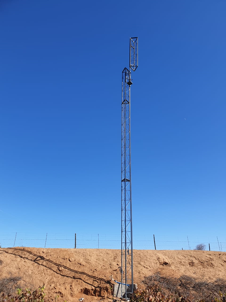
A custom 18 m mast was built for this project. It was a great challenge to get everything aligned and perfectly straight over four sections (2 x 6 m and 2 x 3 m). One critical part of the mast design was a cart that could be hoisted up and down on the tower by a winch. ZS1SC masterfully executed the construction and raising of the mast. The first two 6 m sections were lifted in one go, with the last two 3 m sections installed by using the cart. This was the proving ground that gave the confidence that the cart will work for the antenna building process. The cart runs on two rails made from angle iron and is supported by 12 bearings, 3 per corner.
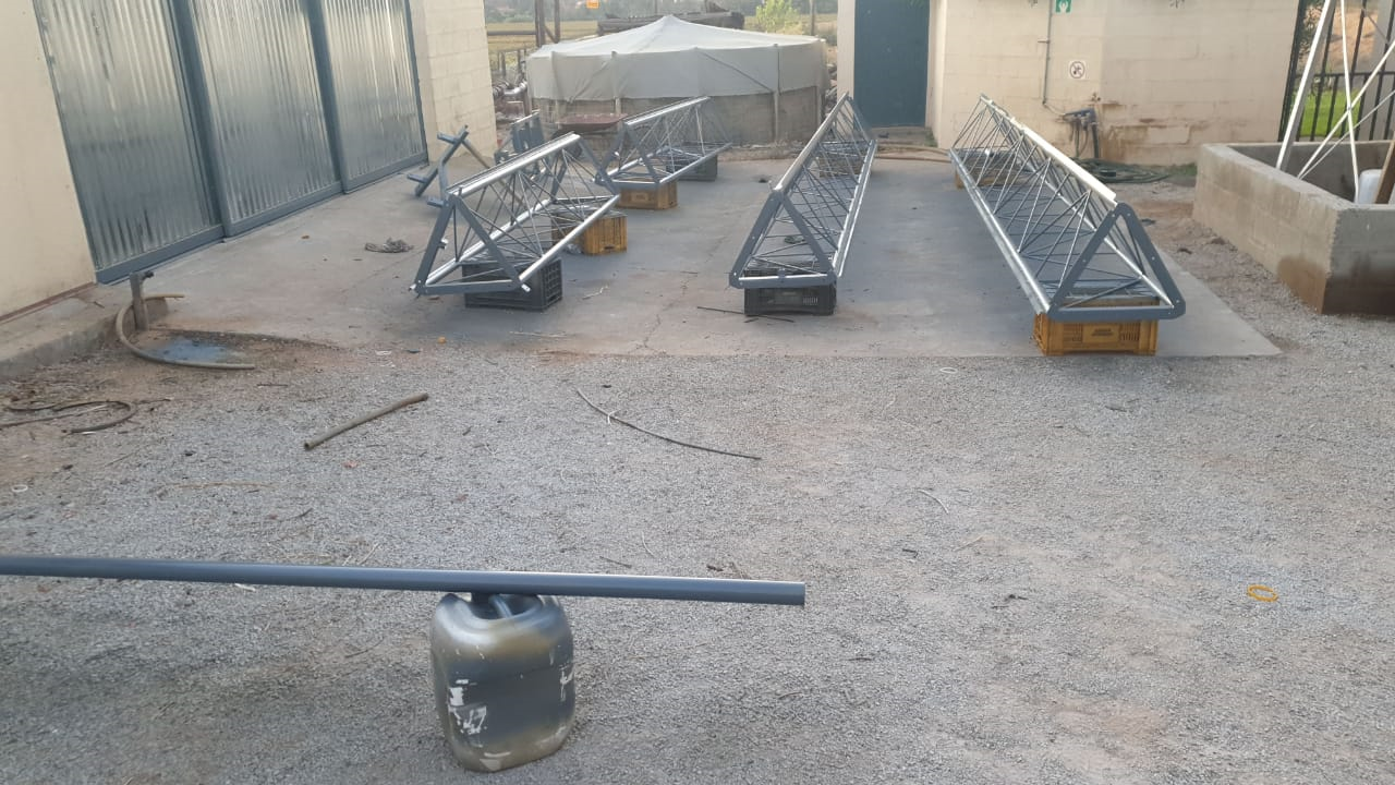
It was then time to design the antenna itself. 22 mm fibreglass rods were selected for the spreader arms, with a custom mild steel hub. All mild steel was sprayed with Sigma prime 200 and topcoat (both with hardener) for protection against the weather. From the preliminary wire lengths from G3TXQ and some other online sources, a 6.5 m radius (13 m diameter) was selected for the antenna. A 3 mm paracord was used for all ropes (perimeter and support).

From research, it was suggested to feed the 30 m and 40 m antennas separately. On each of the bands, a 1:1 balun was installed at the feed point made from two x FT240-43 core material and 18 AWG PTFE wire. The design from DG0SA was doubled up from one core to two x FT240-43 cores to be able to handle 1.5 kW.
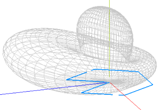
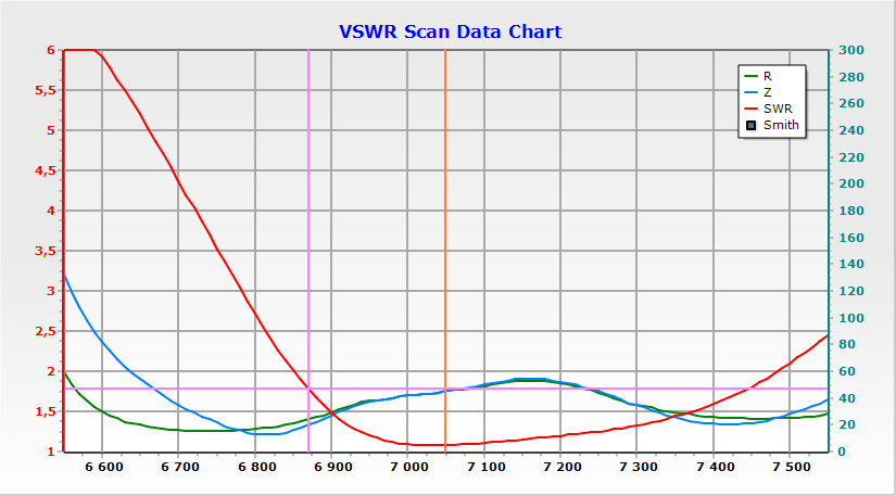
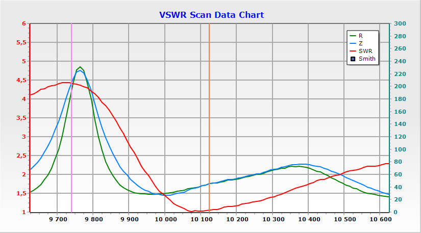
MMANA-GAL basic was used for modelling. Multiple versions of the wire lengths and spacing were modelled, using a spreadsheet to calculate the wire length and coordinates for each iteration. For the driven elements 2.5 mm house wire was used and 1.5 mm house wire for the reflector. The choice of 2.5 mm house wire was to get as broad as possible bandwidth, as low as possible SWR and close as possible to 50 ohm impedance over the entire 30m and 40m bands. The end results achieved were almost 1:1.1 SWR over the band. See details below.
The total weight of the antenna is estimated in the 45 kg to 50 kg range. The spreaders were 30 kg, the hub and centre support were 15 kg, with the wire and rope still to be taken into account.

The last big mechanical design choice required was focussing on how the antenna will ride on the cart and not bind with the mast. Numerous options were evaluated and a custom-built horizontal swinging hinge was selected as the best solution.
Hereafter the wire lengths had to be “fine-tuned”. This delivered one of the biggest curve balls to the team. It became necessary to raise and lower the antenna repetitively due to erratic and wave-like readings/sweeps on the 30 m antenna. However, the problem was finally resolved by replacing the 30 m balun and feedline. The original G3TXQ lengths didn’t work well. The 40m antenna lengths could just be adjusted, but the 30m antenna needed to be redesigned from first principles. The write up on tuning for the classic and broadband versions of the hexbeam was a useful resource for this design process.
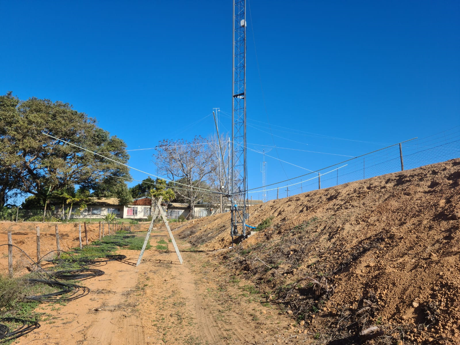
During the tuning process, a few short cuts were found. Lifting the antenna to +_9 m (this was around ¼ wave for 40 m band, which was the lowest band) off the ground was good enough to get a clear view of the performance. The antenna’s resonant frequency per band furthermore increased by about 350 Khz when raised from the ground to the 9 m mark. The final lengths used are listed in the table. The antenna resonated about 400 Khz lower than modelled.
| Element | 30 m | 40 m |
| Director | 7.48 m | 10.61 m |
| Reflector | 14.14 m | 20.47 m |
| End spacing | 0.85 m | 1.21 m |
The final step was to take the antenna to the full 18 m and swing over the hinge and put the lock bolt in. High winds caused this step to be delayed for a frustrating two days.
On completion of the antenna, over 250 contacts were made in under four hours. Some empirical testing confirmed the +_5 db front to back ratio expected. Compared to an inverted V, the antenna also gives about 5 S point gain, which is exactly as predicted and expected.
Although the process was time-consuming and little to no information was available to inform the process, the performance of the antenna and learning experience was definitely worth all the time and energy.